|
The focal plane shutter artifact in
certain digital
cameras Andrew
Davidhazy 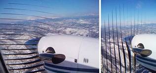 Digital cameras record images in many different ways. Some use a separate mechanical shutter to allow light to affect the individual photo-sensors for a predetermined period of time. Others turn the sensors on electronically and simultaneously for a predetermined period of time. Yet others extract information from the sensor by sequentially transferring data starting at the top of the frame until they get to the bottom. It is this latter type that is represented by the photograph referenced above. The scanning nature of the image acquisition step by this type of camera can be simulated by the manner in which a flat-bed scanner scans material placed on its platen. Manufacturers are careful to point out that users should keep the cover closed while the scanner is scanning. One reason for this is that if the subject being scanned moves then an imperfect reproduction of the original will be the result. In summary this means that the scanner can not deal with moving subjects and reproduce them accurately. For accurate reproduction a simultaneous record of the subject must be made. For this there are area arrays such as built into higher end digital cameras like in DSLRs and most consumer grade cameras. But when it comes to digital cameras built into phones the situation is more variable. These cameras are most often equipped with CMOS, as opposed to CCD, sensor arrays and these lend themselves to line-by-line extraction or progressive of image data. Although neither approach is guaranteed to be used by all digital cameras, since both types can be made to record images sequentially, the camera that took the above photograph was equipped with just such a method for image extraction. Sometimes this is called a "rolling" shutter approach. To demonstrate how the artifact is produced I decided to use my Canon flat-bed scanner as the recording instrument. I built a simulated propeller by adding 4 spokes of masking tape to a clear CD protective disk. The central hole of the disk was just right to accept a pen through its central hole. I taped the pen to the disk. I located a drawing aid that happened to have a hole just the right size to pass the pen through. This allowed me to twirl the pen which rotated the simulated propeller just above the glass surface of the scanner's platen. After conducting some preliminary "twirls" it was obvious that the system would work. But it needed refinements in set-up and understanding of the recording process. The scanner was used only in the PRESCAN mode, and the image produced copied from the screen. The reason for this was that in the SCAN mode the process was so slow that it became hard to make the propeller disk rotate at a steady rate. Directional arrows were added to the scanner platen because it was not at first obvious that the resulting prescan image would need to be flipped left to right. The "camera" was really looking at the rotating disk from below and so left-right orientation was inverted from that point-of-view. Ultimately a series of records were made and assembled into a visual technical report that can be seen in the images below. 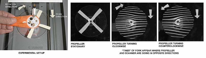 This is essentially the manner in which the experiment was set-up and the results of rotating the simulated propeller at a fairly rapid rate as the flat bed scanner was acquiring a prescan. The next set of images was acquired by rotating the disk at a number of rates starting off slowly and gradually increasing the rotation rate. It is obvious that as the rate increases the resulting artifacts "develop" into the reproduction acquired at the fastest rotation rate I was able to achieve and which are shown in the previous illustration 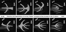 Finally, below once again are the original photographs that were sent to me marked up with the rotation direction of the propellers (they all turn in a counter clockwise direction when viewed from the front and so clockwise when viewed from the rear!) and the scanning process used by the camera to capture image data in a sequential manner takes place from bottom of the sensor upwards (when camera is held so long frame direction is horizontal) and thus from top of the image towards the bottom when viewing the image on the camera screen. It is as shown from the previous illustratins that one has to keep in mind the scanning direction. As stated earlier and as shown in an experiment illustrated later, within this camera the scanning direction is from bottom to top and thus at the subject from top to bottom because within the camera the image is inverted and reversed left to right. It is the "inverted" nature of the optical image that makes the scan at the subject effectively happen from top to bottom such as shown in the left hand picture. The prop blades naturally align with the scanning direction of the photo-sensor. In the left photograph they travel horizontally from bottom to top at the subject and line up with the horizon. For the right hand picture the photographer turned the camera 90 degrees and so the propeller blades now preferentially align in the vertical direction since the scanning action is now perpendicular to the horizon. 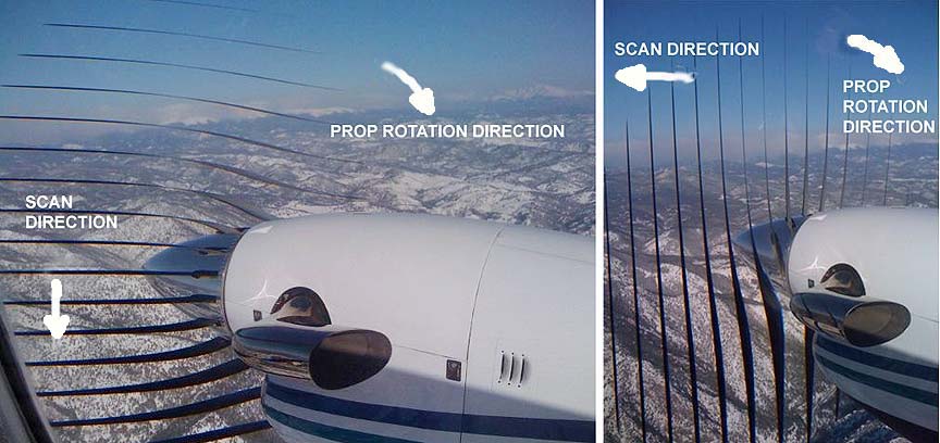 I then did a quick test to determine postivley the scanning direction in a particular phone camera. The iPhone. I knew that the propeller blades when viewed from the rear turned clockwise. I checked this as I stepped off the plane on which I had just flown myself. I made sure to note the position of the camera lens for each of the photographs so I would know what the camera orientation was for each. Note that for the picture on the upper right the blades form the "tines of a fork" pattern typical of the blades moving in the opposite direction of the scanning line. In the picture at lower right (camera "upside down so to speak) they are traveling in the same direction and in the picture on the left they are moving to the right while the scaning action must be taking place from right to left. The "fork" shape to the blades is a result of the fact that the blades and the scanning action are moving in opposite directions. Due to this more blades can pass by the scanning line then when they are moving in the same direction. Effectively the relative speed between the blades and the scanning line is greater when they are moving in opposite directions than when in the same direction. Since the scanning line moves at a consistent pace more blades are able to pass over the line in a given a=mount of time when they travel counter to the direction in which the scannin line moves then when the two are moving in the same direction. It is all a matter of relative speeds! 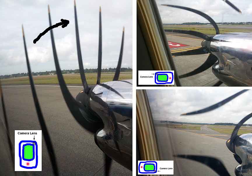 So there you have it. Another photographic anomaly, long associated with what is called focal plane shutter distortion, has resurfaced in the digital realm. In this latter case, however, the device that mimics the moving slit of the focal plane shutter is effectively much finer than the rather large and slow moving slit in the mechanical focal plane shutter. This accounts for the relatively excellent sharpness of the rotating blades of the propeller. Distortion remains, however. One of these days I will make a record with a focal plane shutter of the propeller and have a direct comparison. At this time, alas, I don't have such a comparison but hope to make it soon! Added in December 1985: I was perusing a vintage US Camera Annual from 1943 and this photograph "jumped up" out of a page. Nothing less than what I was going to do with my focal plane shutter equipped DSLR but it turns out I do not have to make a photograph myself to prove the point that this is not a "modern" phenomenon. 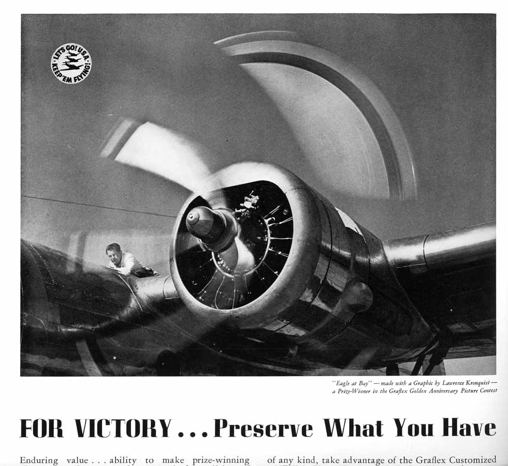
If you found this interesting or useful or you want to discuss this
feel free to send me an email at Andrew Davidhazy,
andpph@davidhazy.org
A set of Qustions and Answers was sent to me by Konstantin Othmer, kon@coremobility.com, and are included here with his permission. They help with some of the concepts discussed above. A friend and I were thinking about this effect in a video he took and we found your excellent web page: After reading the page, I still didn't grock it, so I wrote my own Q&A to figure it out; I've convinced myself I now "get it". Not that your explanation wasn't excellent - I'm just a bit slow! Your page is really outstanding! Thanks for the great write-up and really cool experimental results with the scanner. Konstantin Q: Is each line the same blade or a different blade? A: Trick question! At the top and bottom, each line is one blade - first on the way up and then on the way down. In the middle, there is one line where the blade goes the same direction as the scan, and multiple lines on the other side. The multiple lines are each one blade, but the single line is all four blades! Q: How fast are things moving? A: A blade is at 1800 RPM, or 30 RPS. Assume scan is at 30 FPS. With four blades, each blade appears at every point in the frame once, and you should see four lines on the side where the blade and the scan are going the same direction, and eight lines on the side where they are going the opposite direction. Assume clockwise blade and top to bottom scan. On the right side, blade and scan are going the same direction. Blade 1 intersects scan from 0 to xx Blade 4 intersects scan from just before 1/2 to just after 1/2 Blade 3 intersects scan from xx to 1 Blade 2 never intersects the scan on the right hand side! On the left hand side, blade and scan are going opposite direction: Blade 4 intersects part way, probably 1/8th down, drawing left to right, downward sloping line to the center point Blade 3 intersects in the 2nd part of the way down, probably about 1/4th, downward sloping line to center point and stop Blade 2 intersects starting at 1/2way point, makes very thin line to center point Blade 1 intersects before the ¾ point and scribes thin line sloping down to right Blade 4 intersects just before the end and scribes an upward sloping line all the way across In this case, the scan intersects three blades on the right and five blades on the left! On the right you have three lines, two that go all the way across and one that goes to the center. On the left you have five lines, two that go all the way across, and three that go into the center. Q: Is the blade faster or the scanner faster? A: At 1800 RPM, the blade moving is twice as fast as the camera scanner at (30 fps). It will appear very thin when its going the opposite direction. Imagine the blade starting at 12 and turning clockwise. When the blade is ¼ of the way around (at 3), the scanner is 1/8th of the way down. So the blade and the scanner only intersect for the very top piece after which time the blade outruns it. The next blade is not far behind, and when the scanner is at 1/8th of the way down, the next blade is at noon, having already drawn the left part of the line which is sloping down since the outer most part will hit the scanner first, and the scanner is going down. The faster the propeller spins, the more lines you will get. Each blade "draws" a horizontal line as it passes through the scanner "window". It passes through with sine wave speed - fast on the ends, slower in the middle, and then fast on the ends again. QQ:You would think the lines would be much wider on one side than the other, and a lot fatter in the middle than on the tips, but they aren't. Not sure I get why that is. Maybe I don't understand it after-all! The easiest way to grock this is to imagine looking through one gap in a horizontal blind, and imagine a propeller spinning on the other side. You'll see a dot move from one side to the other - taken across time, it draws a line. and this is a photograph made by Loret Steinberg illustrating the effect on her winshield wiper as she was driving on the NYS Thruway! 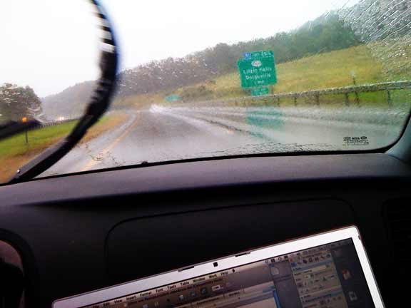 NOTE: When this article was originally prepared I had wrongly assumed that props generally turned clockwise when viewed from the front and the scanning action in the camera was from top to bottom at the sensor (bottom to top at the subject). Both were incorrect assumptions but the analysis was still OK. Below is the message that prompted the "review" of propeller rotation direction: I am very interested in your explanation of the focal plane shutter artifact as it relates to the digital images of the aircraft propeller. Your simulation device is very clever and helps in the understanding of this digital phenomenon I am a radiologist so I have an interest in this from the standpoint of patient motion artifact created by breathing or cardiac motion during digital chest imaging. I am also a pilot which drew me to your paper since it was quoted in an aviation forum. The engine nacelle seen in the pictures is of a mid sized, twin engine, turboprop aircraft -- probably a Beechcraft King Air series. As presented, the pictures are of the right engine as seen by the right seated co-pilot who is behind and inboard of the propeller arc. Counter to your statement in the paper, almost all aircraft engines actually turn in a counter clockwise (CCW) direction when viewed from the front. (There are only a few European engines that turn in the opposite, CW direction-) So, the camera would have to be looking at a disc rotating in a clockwise direction since the camera is behind the arc. The only circumstance that could confuse this scenario is that the picture was actually made of the LEFT engine by the pilot in the left seat and then the image was reversed prior to printing, but that would also have reversed the presentation of the artifact. I am interested in your thoughts with the above in mind. Best regards Crispin Spencer, CSPENCER@ATLANTIC.NET
|